
Control Model at GDSF
+5
craig@STW
Graeme81
Robfishman
Rickster
highpressure
9 posters
Page 1 of 1

Control Model at GDSF
![]() highpressure Wed 31 Aug 2011, 9:02 pm
highpressure Wed 31 Aug 2011, 9:02 pm
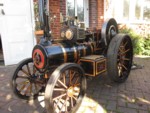
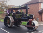
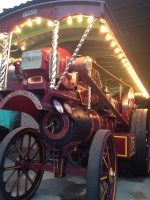
Here they are. Looks seriously impressive now and certainly reassures that the next few kits are well and truely under way. Hopefully this will finally silence all those doubters that seem to be forever expecting the worst... Jealously is such a poor trait....


Excuse the 4th picture I seem to have fallen over trying to take a shot of the casting for the genny. Looks very smart though. The drive gears were very well finished and from what I can gather simply fitted on without any hassle. They slipped in and out without any binding at all and are a thing to behold. The casting for the diff housing looks like a back breaker!!! Not passing any comment on the weyshaft bracket!!!
Roll on the next few months.
Excuse the 4th picture I seem to have fallen over trying to take a shot of the casting for the genny. Looks very smart though. The drive gears were very well finished and from what I can gather simply fitted on without any hassle. They slipped in and out without any binding at all and are a thing to behold. The casting for the diff housing looks like a back breaker!!!
Roll on the next few months.
highpressure- Number of posts : 1096
Age : 57
Location : West Sussex, 4" DCC Road Loco
Registration date : 2008-06-18 -

Re: Control Model at GDSF
![]() Rickster Wed 31 Aug 2011, 9:10 pm
Rickster Wed 31 Aug 2011, 9:10 pm
Wow !! Well done for the pictures. Looks absolutley fantastic. I can't believe there are actually people out there that are doubting this new Company and its products.
The whole thing is nothing short of fabulous. Well done all at STW - as everyone else, I can't wait for the coming kits.
cheers
Rick
The whole thing is nothing short of fabulous. Well done all at STW - as everyone else, I can't wait for the coming kits.
cheers
Rick
Rickster- Number of posts : 267
Location : canterbury, Kent
Registration date : 2010-02-19
Re: Control Model at GDSF
![]() Rickster Wed 31 Aug 2011, 9:11 pm
Rickster Wed 31 Aug 2011, 9:11 pm
Just noticed, even the eccentrics are radiused off as per full size - you don't often see that in any scale !
Superb !
Superb !
Rickster- Number of posts : 267
Location : canterbury, Kent
Registration date : 2010-02-19
Re: Control Model at GDSF
![]() Robfishman Wed 31 Aug 2011, 9:40 pm
Robfishman Wed 31 Aug 2011, 9:40 pm
Looks very impressive indeed,
Hope you had a good day.
Hope you had a good day.
Last edited by Robfishman on Wed 31 Aug 2011, 9:44 pm; edited 1 time in total
Robfishman- Number of posts : 1061
Age : 49
Location : Chandlers Ford Hants 4" showmans & 4" Roller
Registration date : 2010-11-26 -
Re: Control Model at GDSF
![]() Graeme81 Wed 31 Aug 2011, 9:42 pm
Graeme81 Wed 31 Aug 2011, 9:42 pm
than you for the pictures - can you please post more! one of the complete engine in the shot

Graeme81- Number of posts : 178
Location : Ireland
Registration date : 2009-05-25
Re: Control Model at GDSF
![]() craig@STW Thu 01 Sep 2011, 7:57 am
craig@STW Thu 01 Sep 2011, 7:57 am
looking at those pics i gotta say that does not represent the true stage that we are at in production. the safety valve and governor are stock items from our 4inch Burrell and a few of the other parts must of been finished as one-offs for the shows. but yes, we do have all the generator castings in and the con rods etc are all done 

craig@STW- Number of posts : 1410
Location : location Location
Registration date : 2010-05-06
Re: Control Model at GDSF
![]() Vapor Thu 01 Sep 2011, 9:42 am
Vapor Thu 01 Sep 2011, 9:42 am
Craig,
Do you know or can you find out what the output of the generator is expected to be, I assume this will be dc current I was just wondering what the avaiable power output would.
Do you know or can you find out what the output of the generator is expected to be, I assume this will be dc current I was just wondering what the avaiable power output would.

Vapor- Number of posts : 383
Age : 113
Location : Isle of Wight (2" Burrell & 5" Duchess ex MW)
Registration date : 2008-06-18
Re: Control Model at GDSF
![]() craig@STW Thu 01 Sep 2011, 11:44 am
craig@STW Thu 01 Sep 2011, 11:44 am
Vapor wrote:Craig,
Do you know or can you find out what the output of the generator is expected to be, I assume this will be dc current I was just wondering what the avaiable power output would.
Steve is the one to ask on that, and as he is at the show i won't be seeing him till next week. so if anyone is heading down over the next few days, maybe they could ask him ??
craig@STW- Number of posts : 1410
Location : location Location
Registration date : 2010-05-06
lynnr- Number of posts : 3242
Age : 55
Location : Highland, 4inch showman
Registration date : 2010-08-06
Re: Control Model at GDSF
![]() Vapor Thu 01 Sep 2011, 4:10 pm
Vapor Thu 01 Sep 2011, 4:10 pm
Lynn
Unless it's an alternator or you fit an inverter then AC is not an option
Unless it's an alternator or you fit an inverter then AC is not an option
Vapor- Number of posts : 383
Age : 113
Location : Isle of Wight (2" Burrell & 5" Duchess ex MW)
Registration date : 2008-06-18
Re: Control Model at GDSF
![]() Robfishman Sat 03 Sep 2011, 10:59 am
Robfishman Sat 03 Sep 2011, 10:59 am
Not really knowing much about the technical side, I wonder if an alternator could be installed where the exciter sits?
Robfishman- Number of posts : 1061
Age : 49
Location : Chandlers Ford Hants 4" showmans & 4" Roller
Registration date : 2010-11-26 -
Re: Control Model at GDSF
![]() Vapor Sun 04 Sep 2011, 12:31 pm
Vapor Sun 04 Sep 2011, 12:31 pm
But then it wont look like a generator as would have been fitted.
Vapor- Number of posts : 383
Age : 113
Location : Isle of Wight (2" Burrell & 5" Duchess ex MW)
Registration date : 2008-06-18
Robfishman- Number of posts : 1061
Age : 49
Location : Chandlers Ford Hants 4" showmans & 4" Roller
Registration date : 2010-11-26 -
Re: Control Model at GDSF
![]() Graeme81 Fri 09 Sep 2011, 9:26 am
Graeme81 Fri 09 Sep 2011, 9:26 am
Do you know or can you find out what the output of the generator is expected to be, I assume this will be dc current I was just wondering what the avaiable power output would. .
a full size burrell scenic showmans is puttig out about 28,600 watts from the primary and in around 8,900 from exciter, i am not sure what way this reduces in 4inch scale but im sure there will be plenty of useful power available!
Graeme81- Number of posts : 178
Location : Ireland
Registration date : 2009-05-25
Re: Control Model at GDSF
![]() Vapor Fri 09 Sep 2011, 10:58 am
Vapor Fri 09 Sep 2011, 10:58 am
Graeme81 wrote:Do you know or can you find out what the output of the generator is expected to be, I assume this will be dc current I was just wondering what the avaiable power output would. .
a full size burrell scenic showmans is puttig out about 28,600 watts from the primary and in around 8,900 from exciter, i am not sure what way this reduces in 4inch scale but im sure there will be plenty of useful power available!
Graeme,
The figure of 28.6Kw is quite impressive but I am confused about the exciter I assume this must have been separate from the main (or primary) generator one would also assume that this would be for providing the field current for the main generator and not for external power, all the photos only show one generator so I wonder where the exciter is unless it is housed within the main generator?? Does anyone know?
Secondly 28.6Kw is great but that is just the power output and is a product of the voltage X the amperage which does not tell me what the volts or the amps are if you can find out what either one is then we can work out the other.
Ian
Last edited by Vapor on Fri 09 Sep 2011, 11:00 am; edited 1 time in total (Reason for editing : poor grammer :) and spelling)
Vapor- Number of posts : 383
Age : 113
Location : Isle of Wight (2" Burrell & 5" Duchess ex MW)
Registration date : 2008-06-18
What the generator will do
![]() Steve Traill Fri 09 Sep 2011, 12:26 pm
Steve Traill Fri 09 Sep 2011, 12:26 pm
Electricity is like weight in that it doesn't scale very well, talking to Steve over the Dorset week the generator at the front will hopefully pump out about 30 - 35 amps at 12volts. This will be enough for some 75 x 5watt bulbs to replicate the lights on Ex-Mayor. (75 x 5w divided by 12v = 31.25amps) The electricity produced obviously depends on engine revolutions so there is a balance to be struck on that. As I understand it, & Steve will have to confirm, the same motor/dynamo will be an additional option to fit in the exciter dynamo therefore doubling the capacity of the generating if something else needed to run from the engine. In standard form it will generate enough to light up the engine like Ex-Mayor if thats what you want. Who's going to be first in fitting a mobile phone charging point on the roof!!! could be a money making service at the rally field judging by Dorset last week.

Steve Traill- Number of posts : 800
Age : 67
Location : Illogan Redruth Cornwall
Registration date : 2008-06-29
Re: Control Model at GDSF
![]() FosterGP6NHP Fri 09 Sep 2011, 12:40 pm
FosterGP6NHP Fri 09 Sep 2011, 12:40 pm
A senic engine(full size) has an electrical system that is known as the Ward-Leonard system, basically the main dynamo supplies the ride motors, the auxiliary/exiter dynamo which is separate and behind the chimney belt driven from the main dynamo supplies the rides lights, water pumps etc and exites the main dynamo when required to operate the rides motors. Based upon what Wm. Fosters were using on there 10nhp engines the main dynamo would be a Mather & Platt P8c, 750rpm 280 amps @ 110v DC. The auxiliary/exiter belt driven from the main dynamo would be a Mather & Platt P3c,1350rpm, 80 amps @ 110v DC. The 7nhp machines used a P7c which was 200 amps @ 110v DC.
FosterGP6NHP- Number of posts : 12
Location : Rugby
Registration date : 2011-05-18
Re: Control Model at GDSF
![]() Vapor Fri 09 Sep 2011, 2:44 pm
Vapor Fri 09 Sep 2011, 2:44 pm
FosterGP6NHP wrote:A senic engine(full size) has an electrical system that is known as the Ward-Leonard system, basically the main dynamo supplies the ride motors, the auxiliary/exiter dynamo which is separate and behind the chimney belt driven from the main dynamo supplies the rides lights, water pumps etc and exites the main dynamo when required to operate the rides motors. Based upon what Wm. Fosters were using on there 10nhp engines the main dynamo would be a Mather & Platt P8c, 750rpm 280 amps @ 110v DC. The auxiliary/exiter belt driven from the main dynamo would be a Mather & Platt P3c,1350rpm, 80 amps @ 110v DC. The 7nhp machines used a P7c which was 200 amps @ 110v DC.
Ah at last an answer, I am very familar with the "Ward-Leonard" system of control this also confirms my statment that the "exciter" was controling the main generator/dynamo fields thereby controling the output current of the main generator.
With regard supplying upto 75 12v 5watt filament lamps you could consider using the LED warm white versions which consume much less current and also have a much improved life span this would either allow more lamps to be powered or any other appliances in fact you could fit a 12v to 230vac inverter and even power something that requires 240vac mains
Vapor- Number of posts : 383
Age : 113
Location : Isle of Wight (2" Burrell & 5" Duchess ex MW)
Registration date : 2008-06-18
LED's
![]() Steve Traill Fri 09 Sep 2011, 2:56 pm
Steve Traill Fri 09 Sep 2011, 2:56 pm
Good idea if extra power is needed, personally LED's look a bit too modern for me and they don't have the dimming effect you get with a filiament bulb when the engine revs vary.
Yer pays yer money
Yer makes yer choice
as they say
Yer pays yer money
Yer makes yer choice
as they say
Steve Traill- Number of posts : 800
Age : 67
Location : Illogan Redruth Cornwall
Registration date : 2008-06-29
Re: Control Model at GDSF
![]() FosterGP6NHP Fri 09 Sep 2011, 7:31 pm
FosterGP6NHP Fri 09 Sep 2011, 7:31 pm
Vapor wrote:FosterGP6NHP wrote:A senic engine(full size) has an electrical system that is known as the Ward-Leonard system, basically the main dynamo supplies the ride motors, the auxiliary/exiter dynamo which is separate and behind the chimney belt driven from the main dynamo supplies the rides lights, water pumps etc and exites the main dynamo when required to operate the rides motors. Based upon what Wm. Fosters were using on there 10nhp engines the main dynamo would be a Mather & Platt P8c, 750rpm 280 amps @ 110v DC. The auxiliary/exiter belt driven from the main dynamo would be a Mather & Platt P3c,1350rpm, 80 amps @ 110v DC. The 7nhp machines used a P7c which was 200 amps @ 110v DC.
Ah at last an answer, I am very familar with the "Ward-Leonard" system of control this also confirms my statment that the "exciter" was controling the main generator/dynamo fields thereby controling the output current of the main generator.
With regard supplying upto 75 12v 5watt filament lamps you could consider using the LED warm white versions which consume much less current and also have a much improved life span this would either allow more lamps to be powered or any other appliances in fact you could fit a 12v to 230vac inverter and even power something that requires 240vac mains
From the amount of surviving senic engines being Burrell's a lot of people think that the senic engine was thought up by Burrell's, WRONG, it was thought up by Wm Foster's.
How would the LED's cope with the revs/volts rising?
FosterGP6NHP- Number of posts : 12
Location : Rugby
Registration date : 2011-05-18
Re: Control Model at GDSF
![]() Robfishman Fri 09 Sep 2011, 8:44 pm
Robfishman Fri 09 Sep 2011, 8:44 pm
Steve Traill wrote:Electricity is like weight in that it doesn't scale very well, talking to Steve over the Dorset week the generator at the front will hopefully pump out about 30 - 35 amps at 12volts. This will be enough for some 75 x 5watt bulbs to replicate the lights on Ex-Mayor. (75 x 5w divided by 12v = 31.25amps) The electricity produced obviously depends on engine revolutions so there is a balance to be struck on that. As I understand it, & Steve will have to confirm, the same motor/dynamo will be an additional option to fit in the exciter dynamo therefore doubling the capacity of the generating if something else needed to run from the engine. In standard form it will generate enough to light up the engine like Ex-Mayor if thats what you want. Who's going to be first in fitting a mobile phone charging point on the roof!!! could be a money making service at the rally field judging by Dorset last week.
That’s my idea of powering a 4" scale fairground ride straight off the engine out the window without a degree in electrical engineering, some clever wizardry and a working exciter dynamo. But i'll not be beaten that easily.
Robfishman- Number of posts : 1061
Age : 49
Location : Chandlers Ford Hants 4" showmans & 4" Roller
Registration date : 2010-11-26 -
» Control model pictures
» The Control model
» Showmans Control Model
» Control model steaming
» Roller Control Model
» The Control model
» Showmans Control Model
» Control model steaming
» Roller Control Model
Page 1 of 1
Permissions in this forum:
You cannot reply to topics in this forum|
|
|